Your basket is currently empty!
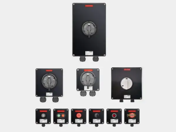
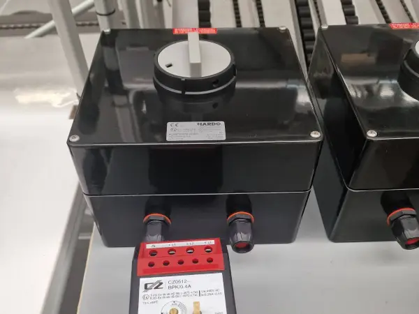
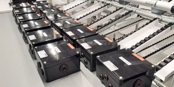
Atex motor switches | Hardo
585,00 €
Applied protections: ► overload protection► undervoltage protection (optional)► phase failure protection► short-circuit protection► thermal protectionOverload trip range 0.1 to 25AMotor switching capacity in AC-3 category up to 440V / 25AMain contacts from 1 to 10 mm² (from 6 to 10 mm²using collets)Auxiliary contacts 1 to 2.5 mm²Auxiliary contact capacity AC15 1A / 230VRated switching capacity high – up to 65 kA
Description
Certification:Gases: 1 and 2 | Dusts: 21 and 22 Atex zones
Switch positions: On | Off
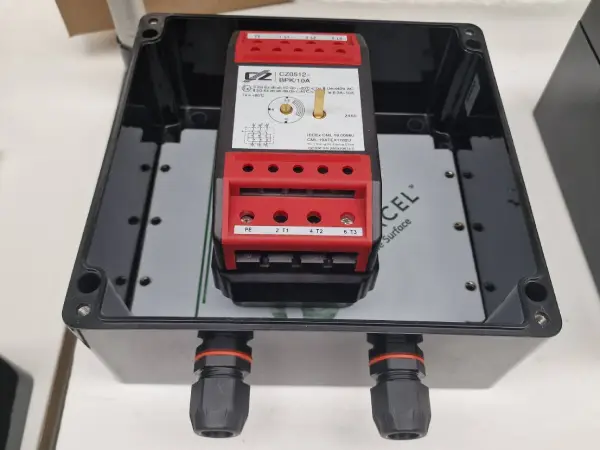
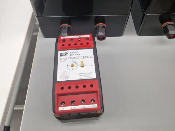
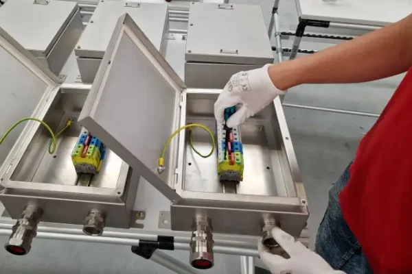
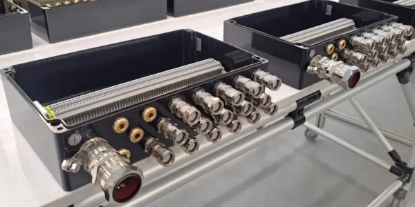
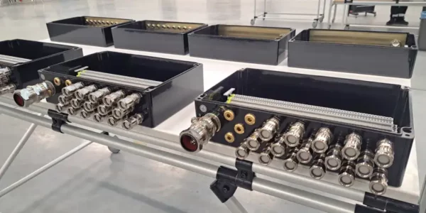
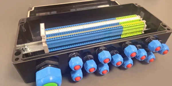
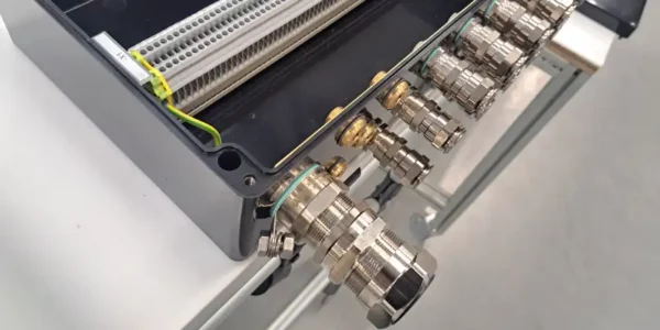
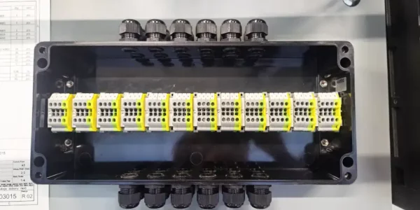
Contacts: 3L + NO, NC, PE, D1, D2
Overload trigger: 0,1-25A
ATEX marking:
![]() II 2 G Ex db eb IIC T4/T5/T6 Gb
II 2 G Ex db eb IIC T4/T5/T6 Gb
![]() II 2 D Ex tb IIIC T85°C Db
II 2 D Ex tb IIIC T85°C Db
IECEx marking:
Ex db eb IIC T5/T6 Gb
Ex tb IIIC T85°C Db
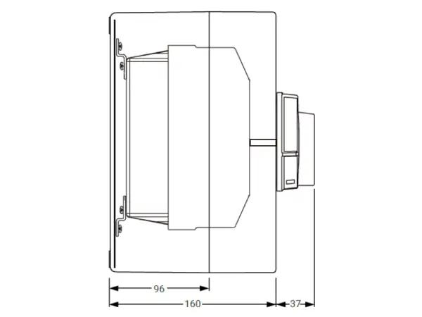
Material: GRP (anti-static glass fibre reinforced polyester)
Ambient temperature: -55°C to +60°C
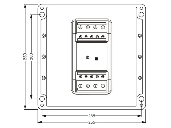
IP rating: IP66/IP68
Certificates
Download
Instructions
Download
Overload trip range
| Overload trip range | Rated switching capacity (making & breaking) |
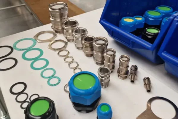
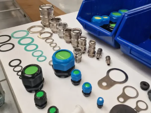
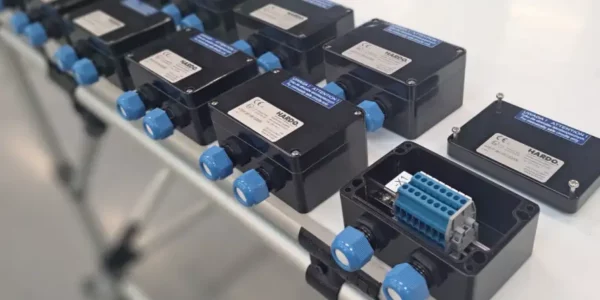
Cable glands | Order No. |
|---|---|---|---|
| 0.1 – 0.16 A | 65 kA | 2 × M25 | Add to basket |
| 0.16 – 0.25 A | 65 kA | 2 × M25 | Add to basket |
| 0.25 – 0.4 A | 65 kA | 2 × M25 | Add to basket |
| 0.4 – 0.63 A | 65 kA | 2 × M25 | Add to basket |
| 0.63 – 1 A | 65 kA | 2 × M25 | Add to basket |
| 1 – 1.6 A | 65 kA | 2 × M25 | Add to basket |
| 1.6 – 2.5 A | 65 kA | 2 × M25 | Add to basket |
| 2.5 – 4 A | 16 kA | 2 × M25 | Add to basket |
| 4 – 6.3 A | 16 kA | 2 × M25 | Add to basket |
| 6.3 – 10 A | 16 kA | 2 × M25 | Add to basket |
| 10 – 16 A | 16 kA | 2 × M25 | Add to basket |
| 16 – 20 A | 12 kA | 2 × M32 | Add to basket |
| 20 – 25 A | 12 kA | 2 × M32 | Add to basket |
1 – basic version without trigger
undervoltage and auxiliary contacts
3 – with auxiliary contacts 1NO + 1NC
with undervoltage trigger and
auxiliary contacts 1NO + 1NC
2 – with undervoltage trigger
Technical data for motor circuit breakers for potentially explosive atmospheres
Atex motor circuit breakers of the HCS1P series are designed for operation in potentially explosive atmospheres, in zones 1, 2, 21 and 22. Their primary type of protection in the context of explosion safety is Ex e protection (i.e. reinforced construction). In addition, Ex motor circuit breakers have overload protection and can be equipped with undercurrent protection and auxiliary contacts (1NO + 1NC)
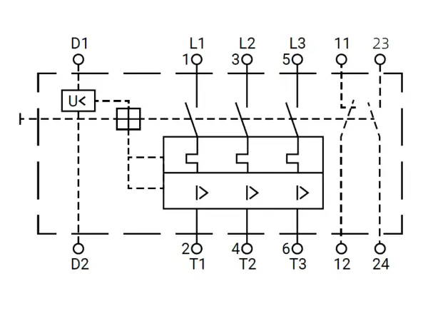
Electrical diagram
| Section | Terminals | What to Connect | Operational Notes |
|---|---|---|---|
| Main power circuits | L1 • L2 • L3 (input) → T1 • T2 • T3 (output) | Three-phase supply ↔ motor | Operating current set by 0.1–25 A trip. Main contacts open instantly on short-circuit or any trip activation. |
| Protective earth terminal | PE | Protective conductor of enclosure / motor frame grounding | Mandatory in Ex zones for potential equalisation. |
| Undervoltage release (U) | D1 – D2 (sometimes A1 – A2) | 230 V AC coil (or other rated voltage) | Coil must be energised to allow closing. Voltage dip below ~70 % UN triggers immediate trip and blocks automatic restart. |
| Auxiliary contacts | 13-14 (NO) & 21-22 (NC) |
13-14: “breaker ON” signal (closes when engaged) 21-22: “breaker OFF” signal (opens when engaged) |
AC-15 1 A / 230 V rating. Suitable for indicator lamps, PLC inputs, interlocks, etc. |
| Holding (latching) loop (optional) | 13-14 in series with D1-D2 | Voltage-holding loop for coil U | Ensures the coil is powered only after the main contacts are fully closed. |
Overload protection and setting ranges (0.1-25 A)
The motor circuit breakers for hazardous areas have built-in overload protection, which protects the motor not only against long-term overload, but also against too frequent starts or short-term overloads that can lead to overheating of the windings. The settings of the motor switches cover the range in 0.1-25 A, and the exact values of the overload ranges are shown in the table below.Wide Range of Sizes:
“It’s fantastic that they offer so many size options. We found the perfect fit for our armored cables without any issues.”
Undervoltage trip (U)
As an option, motor circuit breakers intended for use in hazardous areas can be fitted with an undervoltage trip, the purpose of which is to automatically switch off the device if the supply voltage falls below a safe level. This protects both the motor itself and other plant components from the effects of unstable power supply conditions. Importantly, the switch prevents the motor from restarting automatically when the voltage returns, which is important for safety in Ex zones.Reliable in Harsh Environments:
“We’re using these glands in an industrial setting with extreme temperatures and water exposure. They’ve held up exceptionally well.”
Trigger characteristics (ambient temp. 30°C)
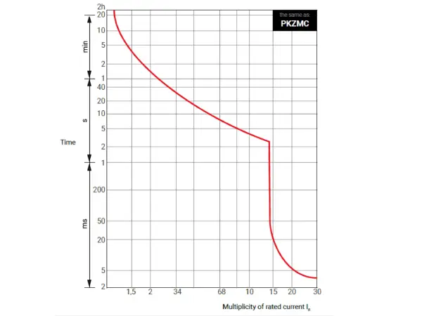
Trip-curve characteristics (30 °C)
| Current multiple × In |
Typical trip time | Practical comment |
|---|---|---|
| 1.05 × In | no trip | Normal inrush or brief load peaks stay energised. |
| 1.2 – 1.3 × In | ≈ 2 – 5 min | Protects against long-term light overload (e.g. high fan load). |
| 1.5 × In | ≈ 30 – 60 s | Trips before windings reach critical temperature. |
| 2 × In | ≈ 8 – 20 s | Heavy overload; fast thermal protection. |
| 4 × In | < 2 s | Partial short or locked rotor; quick disconnect limits damage. |
| 6 – 10 × In | milliseconds | Full short-circuit; magnetic trip operates almost instantly. |
Chart Description
The graph illustrates the relationship between trip time and overload current expressed as a multiple of the rated current In for the HCS1P motor-circuit breaker. The curve is a typical inverse-time characteristic—the higher the overload, the faster the breaker disconnects the motor.
What the curve tells us
Over-temperature protection – with light overloads (1.2 – 2 × In) the motor may run briefly, but once the thermal limit is exceeded the breaker trips.
Fast short-circuit trip – at 6 – 10 × In the magnetic release operates almost instantaneously, minimising arc energy and equipment damage.
Application versatility – one curve covers both light and heavy starts, simplifying protection selection in Ex installations.
In practice: if a motor inrush briefly reaches 4 × In but falls below 1.2 × In within a few seconds, the breaker will not trip. However, a sustained 1.3 × In for more than about three minutes will cause a trip before the winding insulation overheats.
Operating principle based on the wiring diagram
The diagram shows the basic connections of the main circuits (L1, L2, L3 – T1, T2, T3), the undervoltage trip control circuit and the auxiliary contacts (13-14 and 21-22). When voltage is applied and the circuit is activated, the motor is switched on. In the event of an overload or voltage drop, the triggers cut the power supply. The operating contact category is AC-3
Auxiliary contacts 1NO + 1NC
Ex motor circuit breakers can be equipped with auxiliary contacts (one NO and one NC) which are independent of the main tracks and can be used for:
- transmission of the circuit-breaker operating status signal to a higher-level system (e.g. PLC),
- activation of optical or audible signalling,
- blocking the start-up of other devices in the system.
The category of auxiliary contacts is AC15 (1A/230V). The terminals for the auxiliary contacts allow the connection of wires with a cross-section of 1 to 2.5 mm².
Trigger characteristics
The graph shows the dependence of the tripping time on the current value (expressed as a multiple of the rated currentIn) at an ambient temperature of 30°C. This characteristic provides an effective response for both light and heavy overloads:
- for high overloads (e.g. 8-10 ×In) – in milliseconds,
- for low overloads (1.2-2 ×In), the response occurs after a few minutes or so.
Switching capacity and motor application
The Ex HCS1P motor circuit breakers are characterised by their high rated switching and breaking capacity – up to 65 kA, which ensures effective operation even in installations with high short-circuit energy. For motor control in category AC3, the device can handle loads up to 440V / 25A.
Switch housing: resistance, safety, environment
The motor circuit breaker housing for hazardous areas is made of unsaturated polyester resin. The product is reinforced with glass fibre and contains mineral fillers. In the event of a fire, the product will not melt, drip or emit excessive smoke. The product does not contain halogens, heavy metals or any substances listed on the REACH SVHC list.
The housing provides high mechanical and chemical resistance.
The outer casing material has additives that reduce electrification, which negates the risk of ignition of explosive atmospheres due to electrostatic discharge.
Industrial facilities
Construction sites
Outdoor installations
Electrical systems in hazardous zones
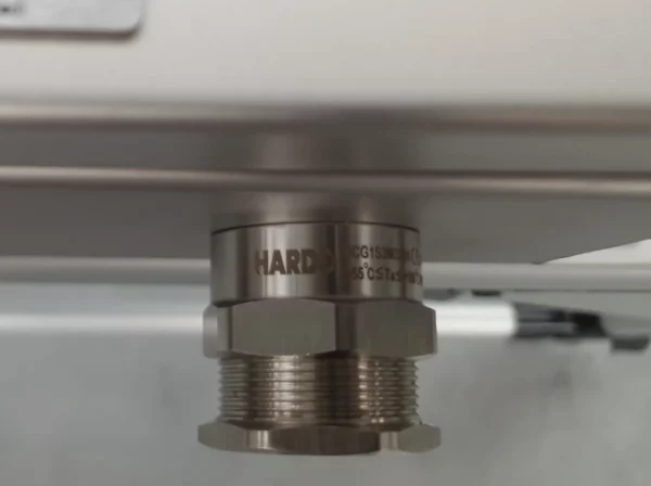
Easy Installation:
User-Friendly: Simple to install with basic tools, minimizing installation time.
Reliable Sealing Mechanism: Includes a secure sealing mechanism that ensures a tight fit around the cable, enhancing safety and performance.
Certifications & Ratings:
ATEX and IECEx Certified: Ensures compliance with stringent safety standards for use in potentially explosive environments.
IP 66/68: Guaranteed protection against dust and water ingress, ensuring reliable performance even in harsh conditions.
Why Choose HCG Cable Glands?
Unmatched Protection: Provides superior protection for armored cables in demanding environments.
Wide Range of Applications: Suitable for a variety of industries including industrial, construction, and electrical installations.
Trusted Certification: With ATEX and IECEx certifications, these cable glands are ideal for use in hazardous zones, ensuring safety and peace of mind.
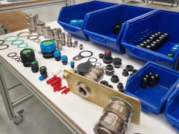
For more details on sizes, thread types, and cable diameter compatibility, please refer to the specifications chart below.
Cable Glands


Additional information
| Overload trip range | 0.1 – 0.16A, 0.16 – 0.25A, 0.25 – 0.4A, 0.4 – 0.63A, 0.63 – 1A, 1 – 1.6A, 1.6 – 2.5A, 10 – 16A, 16 – 20A, 2.5 – 4A, 20 – 25A, 4 – 6.3A, 6.3 – 10A |
|---|